
By Nigel Palmer, Solutions Architect Manager, TT Electronics
Good products demand more than just good design. Here Design for Excellence, or DFx, plays a critical role. Integral to the mission of improving manufacturing processes, DFx is a widely established framework of methods, guidelines, and standards for creating better quality products starting at the concept design phase. Critically, the DFx framework is tapped as early as possible to drive higher quality products, lower costs, and reduced development timelines. Larger corporate entities are typically more familiar with DFx and expect it as a fundamental service from their chosen Contract Electronics Manufacturer (CEM), yet smaller designers may be less aware of its value.
What’s different about DFx vs traditional engineering?
Design for Excellence – or DFx – is a complete package addressing PCB fabrication, assembly, and test, as well as component lifecycle and final assembly where applicable. Generally, traditional engineering methods are not centered on the alignment between a product’s design team and its production and supply chain personnel. In contrast, a highly collaborative DFx process brings in different people, talents, and resources to reduce the design challenges inherent to complex devices. For example, incorporating DFx early in the product’s development enables manufacturing partners to simulate a build, see the product footprint, and effectively visualise what the parts look like. All data prior to production is captured, enabling a smart liaison between an OEM and its supporting design teams.
While every manufacturer has a different approach to DFx, it’s critical to develop a close working partnership with the end customer’s design teams. Larger CEMs can also call upon expertise found within other areas of its own business to help with any unique design or assembly process requirements. Where mechanical assembly requirements relate to low-volume products, ideal DFx operations seek to simplify assembly, breaking down the build into smaller sub-assemblies – for example, reducing the number of fixing screws, standardising fixing screw size head style and type, etc. High-volume production, for instance, systems for high-performance electric vehicles, may seek to optimise mechanical assembly via robotic support.
Analysis tools help evaluate and streamline design considerations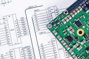
DFx analysis is comparable to building a physical prototype in the virtual world. In this Design for Manufacturing (DFM) phase, analysis of a PCB assembly is performed using a tool such as Siemens Digital Industries’ Valor Process Preparation software to simulate component placement and test access. Tools such as Valor Process Preparation seamlessly integrate the entire PCB manufacturing process with one easy-to-manage platform, enabling detailed review that reduces the number of design revisions. This process uncovers mismatches between the components selected and the physical shape of that part – something that is particularly difficult to visualise without a simulated product layout. Even components that are ultimately accurate for a design’s purpose and performance come in slightly different package sizes and shapes, which vary depending on their part numbering.
Although circuit design may be correct, it is possible and often likely that the parts list used to purchase components from a given distributor may feature an incorrect suffix or prefix. As a result, a slightly different part is ordered and integrated into the real-world, physical prototype. Only then is a problem discovered, causing either a PCB redesign or a pause in the production line while correct parts are ordered and a new prototype is planned and scheduled. At this point in the product development cycle, environmental testing labs may have already been set up to validate product performance. These timelines must also push accordingly.
By injecting DFx into the process – comparing parts lists, the actual electronic CAD designs, and creating a virtual product build – manufacturers reduce room for errors and protect time to market. Further, when a CEM’s various global manufacturing facilities all deploy the same software, an extra layer of security is provided for end-customers requiring seamless global product transitions. Facilities share specific rules that are set up in the Valor Process Preparation tool, allowing a consistent approach in how CAD data is viewed and then merged with materials and components lists to build a virtual PCB. The platform performs multiple design rule checks on the PCB layout. The BOM is virtually compared to its supporting CAD data; with components visualized, the manufacturer is empowered to catch potential errors before assembly takes place.
Real-world results of DFM analysis
By introducing DFM within the design phase, total product cost and NPI iterations can be reduced. In one scenario experienced by TT, the company given the opportunity to provide DFM feedback on a new printed circuit board (PCB) design, prior to the final revision being released to production. Through analysis, it was discovered that some surface mount components were positioned too close to the pin-through connector. Ideally, a minimum of 3mm copper-to-copper clearance is required to allow for automated soldering and de-risking any solder defects. In addition, it was discovered that there were a number of ‘via holes’ in SMD pads which needed to be plugged and capped to prevent solder from wicking away from surface mount pads during assembly and solder reflow. There are many common design errors detected by Valor Process Preparation during the DFM analysis process. Device designers can anticipate DFM analysis to reduce the number of design revisions required to bring a new design to volume production release. The process also improves the reliability of a design by locating manufacturing risks ahead of the production process.
Product development speed must be paired with precision, enbled by DFx. As subcontractor relationships continue to grow in the electronics industry, shared insight and feedback is essential to the processes driving the design and manufacture of a product. Variables always must be considered, but DFx increases overall confidence in product development and facilitates a faster time to market, ensuring that products are reliable and testable. The DFx framework itself provides the interface between design and manufacture to ensure a smooth transition to production – creating an opportunity to determine and correct issues in new products as well as mature, or already developed products.
It is true that a great design team devises a product that fulfills the needs defined by the market. But in this effort, it is essential to design for manufacturability, testability, supply chain, quality, and more before the actual production for efficient processes and a reliable product outcome. Great engineering design practices start with careful consideration of the product requirements to reduce delays and redesign costs later.

